This tutorial will demonstrate the steps to implement a painterly post-processing effect. I wanted this effect for a game that I’m prototyping, although I found that resources for implementing such an effect were scarce. To help other game developers who may be looking for a similar style, I’m documenting the steps I went through to achieve it below.
This tutorial will assume that you have Unity 2020.2 or greater and are using the Universal Render Pipeline stack, although the concepts presented should be portable.
I’ve also created a GitHub repository containing a demo Unity project with the result of following this tutorial.
Table of contents
Approach
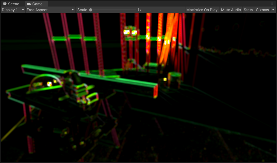
The best-looking examples that I could find use a Kuwahara filter, which smooths images while preserving edges. By adjusting the parameters, some amazing graphical effects can be produced:
However, the basic Kuwahara filter presents a potential issue that may be salient to game development, namely (from the link above):
The Kuwahara filter is also known to create block artifacts in the images especially in regions of the image that are highly textured. These blocks disrupt the smoothness of the image and are considered to have a negative effect in the aesthetics of the image. This phenomenon occurs due to the division of the window into square regions. A way to overcome this effect is to take windows that are not rectangular (i.e. circular windows) and separate them into more non-rectangular regions. There have also been approaches where the filter adapts its window depending on the input image.
This limitation of the Kuwahara filter tends to produce a more mosaic-like effect, which is not what I wanted - for this reason, I opted to go for an approach based on the anisotropic version of the filter, which produces regions of colour that follow edges, producing a more pronounced brush-stroke effect.
A paper released in 2019 by J. Gao, D. Li, and W. Gao called Oil Painting Style Rendering Based on Kuwahara Filter presents an aesthetically pleasing approach. In it, the authors use a multi-scale anisotropic Kuwahara filter to simulate the use of brushes of different sizes. The specific size of the filter kernel is controlled by a saliency map, which highlights areas of greater visual importance and provides finer details in these areas. Finally, using this saliency map as well as edge information computed from the input image, a bump map is generated to provide a sense of layering and thickness of strokes.
The paper describes the following sequence of steps to produce the effect:
- Calculate an edge tangent flow map and a saliency map.
- Filter the image using the anisotropic Kuwahara filter, using the saliency map as the control factor for the kernel size. A higher saliency results in a smaller kernel size, which preserves details, while less important regions use a larger kernel size.
- Create an edge gradient map from the filtered image, and blend this with the edge tangent flow map and the saliency map to compute a bump map.
- Apply lighting effects based on the generated bump map to produce the final image.
My implementation follows a very similar approach, with two main caveats.
Firstly, I’ve used the depth map as a stand-in for the saliency map, as it is relatively
straightforward to compute and can be obtained using the built-in DepthOnlyPass.
Secondly, I use a fixed kernel size for the anisotropic Kuwahara filter due to technical
limitations around unrolling loops in shaders, although I may revisit this in future.
Initial setup
Creating a custom post-processing effect for URP involves creating a custom renderer feature and render pass.
We’ll start with the renderer feature. Create two new C# scripts
(Assets > Create > C# Script) and name them OilPaintingEffect and
OilPaintingEffectPass.
In OilPaintingEffect, replace the contents with the following code:
using System;
using UnityEngine;
using UnityEngine.Rendering;
using UnityEngine.Rendering.Universal;
using UnityEngine.Rendering.Universal.Internal;

public class OilPaintingEffect : ScriptableRendererFeature
{
    public Settings settings;

    private OilPaintingEffectPass renderPass;

    public override void AddRenderPasses(ScriptableRenderer renderer, ref RenderingData renderingData)
    {
        renderPass.Setup(settings);
        renderer.EnqueuePass(renderPass);
    }

    public override void Create()
    {
        renderPass = new OilPaintingEffectPass();
        renderPass.renderPassEvent = RenderPassEvent.BeforeRenderingPostProcessing;
    }

    [Serializable]
    public class Settings
    {

    }
}
And in OilPaintingEffectPass, replace with:
using UnityEngine;
using UnityEngine.Rendering;
using UnityEngine.Rendering.Universal;

public class OilPaintingEffectPass : ScriptableRenderPass
{
    private RenderTargetIdentifier source;
    private RenderTargetIdentifier destination;

    public void Setup(OilPaintingEffect.Settings settings)
    {

    }

    public override void OnCameraSetup(CommandBuffer cmd, ref RenderingData renderingData)
    {
        RenderTextureDescriptor blitTargetDescriptor = renderingData.cameraData.cameraTargetDescriptor;
        blitTargetDescriptor.depthBufferBits = 0;

        var renderer = renderingData.cameraData.renderer;

        source = renderer.cameraColorTarget;
        destination = renderer.cameraColorTarget;
    }

    public override void Execute(ScriptableRenderContext context, ref RenderingData renderingData)
    {
        CommandBuffer cmd = CommandBufferPool.Get("Oil Painting Effect");

        context.ExecuteCommandBuffer(cmd);
        CommandBufferPool.Release(cmd);
    }

    public override void FrameCleanup(CommandBuffer cmd)
    {

    }
}
Now select your Render Pipeline Asset, and select Add Renderer Feature > Oil Painting Effect. Your render pipeline is now set up to use the custom render pass:
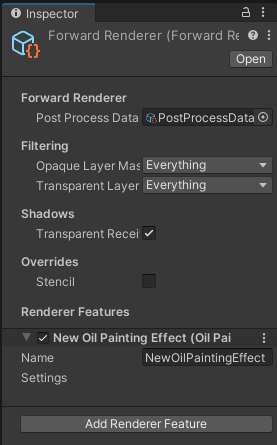
The new renderer feature added to the pipeline.
The Settings property is currently empty, but we’ll change that in a bit.
We have to encapsulate our configuration in this property, as Unity won’t serialize any other
fields defined on a ScriptableRendererFeature.
Structure tensor
The first part we’ll tackle is calculating the structure tensor. The structure tensor is a complex-sounding name for what is essentially the gradient of the image. A simple way to get the gradient is by using a Sobel filter, which is what we’ll use. After we have the gradient, we can use a little bit of maths to calculate the gradient direction vector, the angle of the vector, and the anisotropy. We’ll need this information in a few places, so it’s a good starting point.
So, to start off, create a new image effect shader
(Assets > Create > Shader > Image Effect Shader) and call it StructureTensor.
At the moment, all we’ll do is change the name on the first line:
-Shader "Hidden/StructureTensor"
+Shader "Hidden/Oil Painting/Structure Tensor"
By default, when creating a new image effect shader, the template will have a very simple function - inverting the colours. This is fine for now, as it’ll help us with wiring up the render pass.
Now, open up OilPaintingEffectPass.
We’ll want to make a few changes to be able to use our shader.
Firstly, we’ll add some fields and a constructor:
 public class OilPaintingEffectPass
 {
     private RenderTargetIdentifier source;
     private RenderTargetIdentifier destination;

+    private RenderTexture structureTensorTex;
+
+    private readonly Material structureTensorMaterial;
+
+    public OilPaintingEffectPass(Material structureTensorMaterial)
+    {
+        this.structureTensorMaterial = structureTensorMaterial;
+    }

     public void Setup(OilPaintingEffect.Settings settings)
     {

     }
The material will be created and passed in by the renderer feature, but we’ll get to that soon. Before that, we’ll setup and use the render texture:
 public override void OnCameraSetup(CommandBuffer cmd, ref RenderingData renderingData)
 {
     RenderTextureDescriptor blitTargetDescriptor = renderingData.cameraData.cameraTargetDescriptor;
     blitTargetDescriptor.depthBufferBits = 0;

     var renderer = renderingData.cameraData.renderer;

     source = renderer.cameraColorTarget;
     destination = renderer.cameraColorTarget;

+    structureTensorTex = RenderTexture.GetTemporary(blitTargetDescriptor.width, blitTargetDescriptor.height, 0, RenderTextureFormat.ARGBFloat);
 }

 public override void Execute(ScriptableRenderContext context, ref RenderingData renderingData)
 {
     CommandBuffer cmd = CommandBufferPool.Get("Oil Painting Effect");

+    Blit(cmd, source, structureTensorTex, structureTensorMaterial, -1);
+    Blit(cmd, structureTensorTex, destination);

     context.ExecuteCommandBuffer(cmd);
     CommandBufferPool.Release(cmd);
 }

 public override void FrameCleanup(CommandBuffer cmd)
 {
+    RenderTexture.ReleaseTemporary(structureTensorTex);
 }
Note that we’re blitting twice - once into our temporary render texture using
structureTensorMaterial, and another from the render texture into the destination texture.
It seems a little unnecessary, but the second blit is just for visualisation purposes so that we
can check everything’s working properly.
Now we’ll update OilPaintingEffect to accommodate the changes we’ve just made:
 public override void Create()
 {
-    renderPass = new OilPaintingEffectPass();
+    var structureTensorMaterial = CoreUtils.CreateEngineMaterial("Hidden/Oil Painting/Structure Tensor");
+
+    renderPass = new OilPaintingEffectPass(structureTensorMaterial);
     renderPass.renderPassEvent = RenderPassEvent.BeforeRenderingPostProcessing;
 }
If you save your changes and go back to the Unity Editor, once everything’s recompiled you should notice all the colours in your scene have been inverted, like this:
Inverting the colours using the custom render pass. It’s the computer graphics equivalent of Hello World.
Now we’ll write the shader. First of all, we’ll be using HLSL, not Cg, so we need to make some changes:
 SubShader
 {
-    // No culling or depth
-    Cull Off ZWrite Off ZTest Always
-
-    Pass
-    {
-        CGPROGRAM
-        #pragma vertex vert
-        #pragma fragment frag
-
-        #include "UnityCG.cginc"
-
-        struct appdata
-        {
-            float4 vertex : POSITION;
-            float2 uv : TEXCOORD0;
-        };
-
-        struct v2f
-        {
-            float2 uv : TEXCOORD0;
-            float4 vertex : SV_POSITION;
-        };
-
-        v2f vert (appdata v)
-        {
-            v2f o;
-            o.vertex = UnityObjectToClipPos(v.vertex);
-            o.uv = v.uv;
-            return o;
-        }
-
-        sampler2D _MainTex;
-
-        fixed4 frag (v2f i) : SV_Target
-        {
-            fixed4 col = tex2D(_MainTex, i.uv);
-            // just invert the colors
-            col.rgb = 1 - col.rgb;
-            return col;
-        }
-        ENDCG
-    }
+    Tags { "RenderType"="Opaque" }
+    LOD 200
+
+    Pass
+    {
+        HLSLPROGRAM
+        #include "Packages/com.unity.render-pipelines.universal/ShaderLibrary/SurfaceInput.hlsl"
+        #include "Packages/com.unity.render-pipelines.core/ShaderLibrary/Color.hlsl"
+
+        TEXTURE2D(_MainTex);
+        SAMPLER(sampler_MainTex);
+
+        struct Attributes
+        {
+            float4 positionOS : POSITION;
+            float2 uv         : TEXCOORD0;
+        };
+
+        struct Varyings
+        {
+            float2 uv     : TEXCOORD0;
+            float4 vertex : SV_POSITION;
+        };
+
+        Varyings vert(Attributes input)
+        {
+            Varyings output = (Varyings)0;
+
+            VertexPositionInputs vertexInput = GetVertexPositionInputs(input.positionOS.xyz);
+            output.vertex = vertexInput.positionCS;
+            output.uv = input.uv;
+
+            return output;
+        }
+
+        float3 SampleMain(float2 uv)
+        {
+            return SAMPLE_TEXTURE2D(_MainTex, sampler_MainTex, uv).rgb;
+        }
+
+        half4 frag(Varyings input) : SV_Target
+        {
+            return half4(1 - SampleMain(input.uv), 0);
+        }
+
+        #pragma vertex vert
+        #pragma fragment frag
+
+        ENDHLSL
+    }
 }
+FallBack "Diffuse"
Saving this should result in no visible changes to your scene, as it still inverts the colours.
But now we’ll start writing the Sobel filter.
Let’s add a couple of #defines:
 HLSLPROGRAM
 #include "Packages/com.unity.render-pipelines.universal/ShaderLibrary/SurfaceInput.hlsl"
 #include "Packages/com.unity.render-pipelines.core/ShaderLibrary/Color.hlsl"

+#define PIXEL_X (_ScreenParams.z - 1)
+#define PIXEL_Y (_ScreenParams.w - 1)

 TEXTURE2D(_MainTex);
 SAMPLER(sampler_MainTex);
These definitions will be inlined wherever we use them, but provide a human-readable alias for the
_ScreenParams values.
PIXEL_X and PIXEL_Y represent the width and height of a pixel as a fraction of the width and
height of the image.
This allows us to perform the conversion from pixel space to UV space.
The values of _ScreenParams.z and _ScreenParams.w are supplied by Unity as 1 + 1/width
and 1 + 1/height, which is why we need to subtract one from each.
Now we’ll create our Sobel functions:
 float3 SampleMain(float2 uv)
 {
     return SAMPLE_TEXTURE2D(_MainTex, sampler_MainTex, uv).rgb;
 }

+float3 SobelU(float2 uv)
+{
+    return (
+        -1.0f * SampleMain(uv + float2(-PIXEL_X, -PIXEL_Y)) +
+        -2.0f * SampleMain(uv + float2(-PIXEL_X, 0)) +
+        -1.0f * SampleMain(uv + float2(-PIXEL_X, PIXEL_Y)) +
+
+        1.0f * SampleMain(uv + float2(PIXEL_X, -PIXEL_Y)) +
+        2.0f * SampleMain(uv + float2(PIXEL_X, 0)) +
+        1.0f * SampleMain(uv + float2(PIXEL_X, PIXEL_Y))
+    ) / 4.0;
+}
+
+float3 SobelV(float2 uv)
+{
+    return (
+        -1.0f * SampleMain(uv + float2(-PIXEL_X, -PIXEL_Y)) +
+        -2.0f * SampleMain(uv + float2(0, -PIXEL_Y)) +
+        -1.0f * SampleMain(uv + float2(PIXEL_X, -PIXEL_Y)) +
+
+        1.0f * SampleMain(uv + float2(-PIXEL_X, PIXEL_Y)) +
+        2.0f * SampleMain(uv + float2(0, PIXEL_Y)) +
+        1.0f * SampleMain(uv + float2(PIXEL_X, PIXEL_Y))
+    ) / 4.0;
+}

 half4 frag(Varyings input) : SV_Target
 {
     return half4(1 - SampleMain(input.uv), 0);
 }
The SobelU and SobelV functions together make up the Sobel filter.
SobelU provides the gradient in the X (or U) axis, and SobelV in the Y (or V) axis.
We can visualise them by changing the frag function to map the gradient to the red and blue
channels:
 half4 frag(Varyings input) : SV_Target
 {
-    return half4(1 - SampleMain(input.uv), 0);
+    return half4(length(SobelU(input.uv)), 0, length(SobelV(input.uv)), 0);
 }
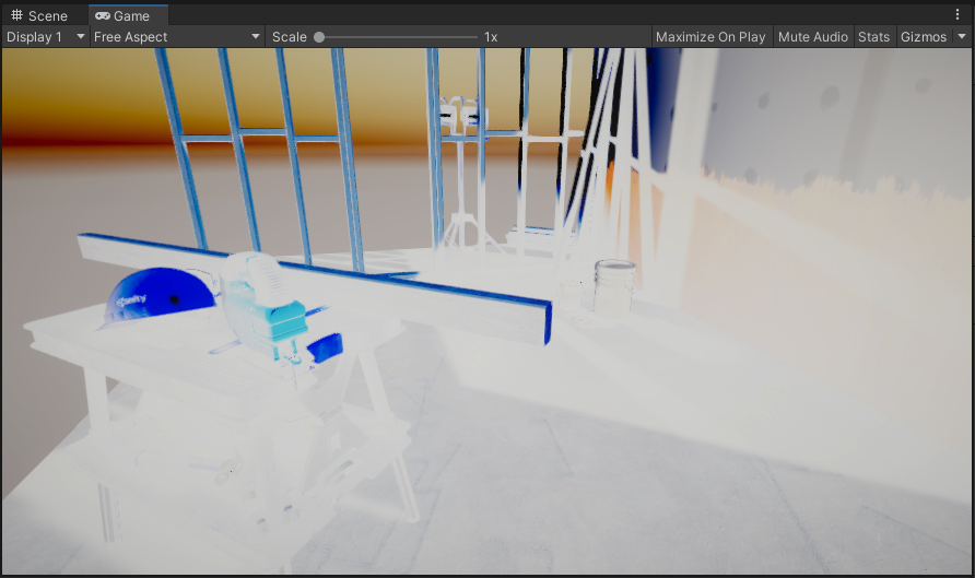
Save again, and your scene should look like this:
The Sobel filter applied to our image. Red represents the gradient along the X axis, blue the gradient along the Y axis. Feel free to stop here if you want to pivot into making a neon bullet hell.
Bear in mind that the post-processing effects built into the URP will be rendered after the pass we’re writing, as can be demonstrated by the slight bloom in the image above. (That was completely intentional and not because I forgot to disable the post-process volume. Ahem.)
We’ll move on now to computing our structure tensor. It’s fairly straightforward, as it’s just a few dot products:
 float3 SobelV(float2 uv)
 {
     return (
         -1.0f * SampleMain(uv + float2(-PIXEL_X, -PIXEL_Y)) +
         -2.0f * SampleMain(uv + float2(0, -PIXEL_Y)) +
         -1.0f * SampleMain(uv + float2(PIXEL_X, -PIXEL_Y)) +

         1.0f * SampleMain(uv + float2(-PIXEL_X, PIXEL_Y)) +
         2.0f * SampleMain(uv + float2(0, PIXEL_Y)) +
         1.0f * SampleMain(uv + float2(PIXEL_X, PIXEL_Y))
     ) / 4.0;
 }

+float3 StructureTensor(float2 uv)
+{
+    float3 u = SobelU(uv);
+    float3 v = SobelV(uv);
+
+    return float3(dot(u, u), dot(v, v), dot(u, v));
+}

 half4 frag(Varyings input) : SV_Target
 {
-    return half4(length(SobelU(input.uv)), 0, length(SobelV(input.uv)), 0);
+    return half4(StructureTensor(input.uv), 0);
 }
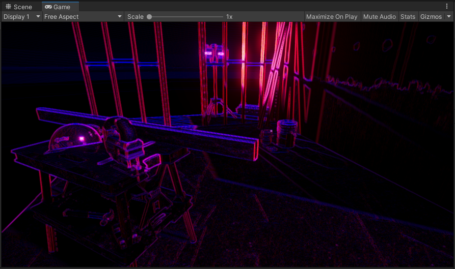
Recompiling the shader will make your scene look like this:
The structure tensor.
The dot product of a vector and itself is equal to its square magnitude. This means that our structure tensor contains the square magnitudes of the gradients in the X axis and the Y axis in the red and green channels. The blue channel contains the dot product of the two Sobel gradient vectors, which provides us with information about the angle between the two vectors. (The dot product of a and b is equal to the magnitude of a, multiplied by the magnitude of b, multiplied by the cosine of the angle between a and b.)
Next, we’ll smooth the structure tensor. The reason for this is given by the paper that introduced the algorithm for anisotropic Kuwahara filtering:
Smoothing the structure tensor is a linear operation on the tensor, but the effect on the eigenvectors is highly non-linear and corresponds geometrically to principal component analysis.
This is pretty jargon-heavy for a single sentence, but the gist of it is that by smoothing the structure tensor, we’re discarding high-frequency information that contributes little to the overall direction of a gradient in the image.
The paper above uses a Gaussian blur to achieve the smoothing, so we’ll do the same:
 float3 StructureTensor(float2 uv)
 {
     float3 u = SobelU(uv);
     float3 v = SobelV(uv);

     return float3(dot(u, u), dot(v, v), dot(u, v));
 }

+float3 SmoothedStructureTensor(float2 uv, float sigma)
+{
+    float twiceSigmaSq = 2.0f * sigma * sigma;
+    int halfWidth = ceil(2 * sigma);
+
+    float3 col = float3(0, 0, 0);
+    float norm = 0;
+    for (int i = -halfWidth; i <= halfWidth; i++)
+    {
+        for (int j = -halfWidth; j <= halfWidth; j++)
+        {
+            float distance = sqrt(i*i + j*j);
+            float k = exp(-distance * distance / twiceSigmaSq);
+
+            col += StructureTensor(uv + float2(i * PIXEL_X, j * PIXEL_Y)) * k;
+            norm += k;
+        }
+    }
+
+    return col / norm;
+}

 half4 frag(Varyings input) : SV_Target
 {
-    return half4(StructureTensor(input.uv), 0);
+    return half4(SmoothedStructureTensor(input.uv, 2.0f), 0);
 }
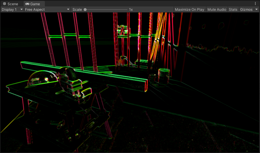
When you save and return to Unity, you’ll notice your edge detection from before has become blurry:
The structure tensor smoothed with a 2-pixel radius Gaussian blur.
We now have our structure tensor, however, in its raw form, it’s not particularly useful to us. It’ll be more useful down the line to know three pieces of information:
- The vector in which direction the gradient changes the least
- The direction of the vector
- The anisotropy of the gradient (i.e. how different the minimum and maximum changes in the gradient are)
Luckily, we have four channels available to us when creating the output of a shader, so we can pack all this information into a single output texture. We’ll assign the vector to the red and green channels, the direction to the blue channel, and the anisotropy to the alpha channel.
We’ll perform our calculations to compute these values in the frag method of our shader:
 half4 frag(Varyings input) : SV_Target
 {
-    return half4(SmoothedStructureTensor(input.uv, 2.0f), 0);
+    float3 t = SmoothedStructureTensor(input.uv, 2.0f);
+
+    float lambda1 = 0.5f * (t.x + t.y + sqrt((t.x - t.y) * (t.x - t.y) + 4.0f * t.z * t.z));
+    float lambda2 = 0.5f * (t.x + t.y - sqrt((t.x - t.y) * (t.x - t.y) + 4.0f * t.z * t.z));
+
+    float2 direction = float2(lambda1 - t.x, -t.z);
+    direction = (length(direction) > 0.0) ? normalize(direction) : float2(0, 1);
+
+    float angle = atan2(direction.y, direction.x);
+
+    float anisotropy = (lambda1 + lambda2 <= 0.0) ? 0.0 : (lambda1 - lambda2) / (lambda1 + lambda2);
+
+    return half4(direction, angle, anisotropy);
 }
The variables lambda1 and lambda2 represent the two eigenvalues of the structure tensor.
The theory behind eigenvalues and eigenvectors is beyond the scope of this tutorial, and at any
rate, the pictures on the Wikipedia article do a better job of explaining what they are than
I can put into words.
Suffice to say, we use them as a one-off calculation to derive the information that we care about
and then never have to think about them again.
You’ll notice that we perform some sanity checks on our output. This is important, as diagnosing where unexpected errors show up in your shader code is a painful experience and I recommend it to no-one.
The direction is a fairly obvious one: it’s possible that we’d encounter a large area of the image that’s completely uniform in colour, in which case there is no gradient in any direction. We then have a zero vector which we’re trying to normalise (which is undefined).
The anisotropy is a bit more subtle: we want to avoid two potential issues.
Firstly, it’s possible that lambda1 and lambda2 add to zero, in which case the division will
fail.
However, we also want to constrain the anisotropy to be positive overall, as we’ll be using it
later on to construct a transformation matrix, and a negative value would provide a negative scale
factor, which would flip our image.
But now that we’ve done our calculations and handled our edge cases, our structure tensor shader is complete - let’s save and go back to Unity to take a look:
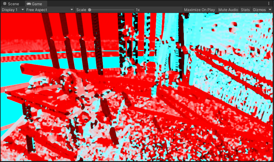
Tada!
Okay, it’s a red and cyan mess. Luckily, that’s completely fine, because the render texture holding this Jackson Pollock-esque masterpiece is going to be used to supply data, and not for its aesthetic qualities.
Anisotropic Kuwahara filtering
Time for the next phase of our post-processing effect. The anisotropic Kuwahara filter will get us most of the way to our final result.
So, create a new image effect shader
(Assets > Create > Shader > Image Effect Shader) and call it AnisotropicKuwaharaFilter.
Replace the contents with the following:
Shader "Hidden/Oil Painting/Anisotropic Kuwahara Filter"
{
    Properties
    {
        _MainTex ("Texture", 2D) = "white" {}

        _StructureTensorTex ("Structure Tensor", 2D) = "white" {}

        [IntRange] _FilterKernelSectors ("Filter Kernel Sectors", Range(3, 8)) = 8
        _FilterKernelTex ("Filter Kernel Texture", 2D) = "black" {}

        _FilterRadius ("Filter Radius", Range(2, 12)) = 4
        _FilterSharpness ("Filter Sharpness", Range(2, 16)) = 8
        _Eccentricity ("Eccentricity", Range(0.125, 32)) = 1
    }
    SubShader
    {
        Tags { "RenderType"="Opaque" }
        LOD 200

        Pass
        {
            HLSLPROGRAM
            #include "Packages/com.unity.render-pipelines.universal/ShaderLibrary/SurfaceInput.hlsl"
            #include "Packages/com.unity.render-pipelines.core/ShaderLibrary/Color.hlsl"

            #define PIXEL_X (_ScreenParams.z - 1)
            #define PIXEL_Y (_ScreenParams.w - 1)

            #define MAX_KERNEL_SECTORS 8

            TEXTURE2D(_MainTex);
            SAMPLER(sampler_MainTex);

            TEXTURE2D(_StructureTensorTex);
            SAMPLER(sampler_StructureTensorTex);

            int _FilterKernelSectors;

            TEXTURE2D(_FilterKernelTex);
            SAMPLER(sampler_FilterKernelTex);
            float4 _FilterKernelTex_TexelSize;

            float _FilterRadius;
            float _FilterSharpness;
            float _Eccentricity;

            struct Attributes
            {
                float4 positionOS : POSITION;
                float2 uv         : TEXCOORD0;
            };

            struct Varyings
            {
                float2 uv     : TEXCOORD0;
                float4 vertex : SV_POSITION;
            };

            Varyings vert(Attributes input)
            {
                Varyings output = (Varyings)0;

                VertexPositionInputs vertexInput = GetVertexPositionInputs(input.positionOS.xyz);
                output.vertex = vertexInput.positionCS;
                output.uv = input.uv;

                return output;
            }

            float3 SampleMain(float2 uv)
            {
                return SAMPLE_TEXTURE2D(_MainTex, sampler_MainTex, uv).rgb;
            }

            float4 SampleStructureTensor(float2 uv)
            {
                return SAMPLE_TEXTURE2D(_StructureTensorTex, sampler_StructureTensorTex, uv);
            }

            float SampleFilterKernel(float2 uv)
            {
                return SAMPLE_TEXTURE2D(_FilterKernelTex, sampler_FilterKernelTex, uv).r;
            }

            float2x2 GetScaleMatrix(float anisotropy, float eccentricity)
            {
                float2x2 s;
                s._m00 = clamp(eccentricity / (eccentricity + anisotropy), 0.1, 2.0);
                s._m11 = clamp((eccentricity + anisotropy) / eccentricity, 0.1, 2.0);
                s._m01 = 0;
                s._m10 = 0;

                return s;
            }

            float2x2 GetRotationMatrix(float phi)
            {
                float cosPhi = cos(phi);
                float sinPhi = sin(phi);

                float2x2 r;
                r._m00 = cosPhi;
                r._m11 = cosPhi;
                r._m01 = -sinPhi;
                r._m10 = sinPhi;

                return r;
            }

            half4 frag(Varyings input) : SV_Target
            {
                float4 tensor = SampleStructureTensor(input.uv);

                float2 v = tensor.xy;
                float phiBase = tensor.z;
                float a = tensor.w;

                float2x2 s = GetScaleMatrix(a, _Eccentricity) * _FilterRadius;

                float3 weightedAverages[MAX_KERNEL_SECTORS];
                float3 standardDeviations[MAX_KERNEL_SECTORS];

                [unroll]
                for (int i = 0; i < _FilterKernelSectors; i++)
                {
                    weightedAverages[i] = float3(0,0,0);
                    standardDeviations[i] = float3(0,0,0);

                    float phi = phiBase + (2.0f * PI * i / _FilterKernelSectors);
                    float2x2 r = GetRotationMatrix(phi);

                    float2x2 sr = mul(s, r);

                    float norm = 0;
                    for (int x = -ceil(_FilterRadius); x <= ceil(_FilterRadius); x++)
                    {
                        for (int y = -ceil(_FilterRadius); y <= ceil(_FilterRadius); y++)
                        {
                            float offsetSqMagnitude = x*x + y*y;
                            if (offsetSqMagnitude / _FilterRadius <= 0.25)
                            {
                                float2 offset = mul(sr, float2(PIXEL_X * x, PIXEL_Y * y));

                                float2 sampleUV = input.uv + offset;
                                float3 sample = SampleMain(sampleUV);

                                float wu = 0.5f + 0.5f * (x / ceil(_FilterRadius));
                                float wv = 0.5f + 0.5f * (y / ceil(_FilterRadius));

                                float2 weightUV = float2(wu, wv);
                                float weight = SampleFilterKernel(weightUV);

                                weightedAverages[i] += sample * weight;
                                standardDeviations[i] += sample * sample * weight;

                                norm += weight;
                            }
                        }
                    }

                    if (norm > 0)
                    {
                        weightedAverages[i] /= norm;
                        standardDeviations[i] /= norm;
                        standardDeviations[i] -= weightedAverages[i] * weightedAverages[i];
                        standardDeviations[i] = abs(standardDeviations[i]);
                    }
                }

                float sumAlpha = 0;
                float3 sumAlphaWeights = 0;
                for (i = 0; i < _FilterKernelSectors; i++)
                {
                    float sigmaSq = abs(standardDeviations[i].r + standardDeviations[i].g + standardDeviations[i].b);
                    float alpha = 1 / (1 + pow(255 * sigmaSq, 0.5f * _FilterSharpness));

                    sumAlpha += alpha;
                    sumAlphaWeights += alpha * weightedAverages[i];
                }

                return half4(sumAlphaWeights / sumAlpha, 0);
            }

            #pragma vertex vert
            #pragma fragment frag

            ENDHLSL
        }
    }
    FallBack "Diffuse"
}
There’s quite a lot to unpack here in comparison to the previous section. The paper outlining the algorithm goes into more detail, but essentially what we’re doing is this:
- Creating an elliptical filter, using the structure tensor to determine the shape and rotation to align along the gradient
- Splitting the filter into a number of sectors
- Sampling the source image, weighting by the filter strength at each point
- Calculating the average pixel value and the standard deviation for each sector
- Adding together the average pixel value of each sector, where sectors with a lower standard deviation contribute more to the final result.
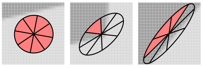
Visualisations of the elliptical filter, from left to right in order of increasing anisotropy. The red shaded sectors indicate those with the largest contribution to the overall result.
You’ll notice that our filter shader has a lot of properties that we need to supply.
We’ll set up the OilPaintingEffect renderer feature to expose properties that we can use to
configure the shader:
 [Serializable]
 public class Settings
 {
+    public AnisotropicKuwaharaFilterSettings anisotropicKuwaharaFilterSettings;
 }

+[Serializable]
+public class AnisotropicKuwaharaFilterSettings
+{
+    [Range(3, 8)]
+    public int filterKernelSectors = 8;
+    [Range(0f, 1f)]
+    public float filterKernelSmoothness = 0.33f;
+    [NonSerialized]
+    public Texture2D filterKernelTexture;
+
+    [Range(2f, 12f)]
+    public float filterRadius = 4f;
+    [Range(2f, 16f)]
+    public float filterSharpness = 8f;
+    [Range(0.125f, 8f)]
+    public float eccentricity = 1f;
+
+    [Range(1, 4)]
+    public int iterations = 1;
+}
Now we have some configurable settings in the Inspector for the renderer asset:
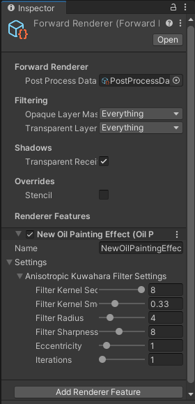
The settings to configure our filter.
The filterKernelTexture doesn’t show up.
That’s because we’ve attached the [NonSerialized] attribute to it.
We’ve done this because we want to generate the texture to represent the filter kernel, for a few
reasons.
Firstly, we don’t want to be able to assign an arbitrary texture to this property, as the filter
kernel has some particular requirements.
Secondly, this texture is completely defined by the number of sectors and the filter smoothness, so
we can avoid forgetting to update the texture when we make changes to the parameters.
Thirdly, this texture doesn’t have any dynamic aspect, so calculating it each frame would be a
waste of GPU cycles.
We’ll set up this texture generation in a moment, but first, we need to make a couple of changes:
 public class OilPaintingEffect : ScriptableRendererFeature
 {
+    private const int FilterKernelSize = 32;

     public Settings settings;

     private OilPaintingEffectPass renderPass;
 public override void Create()
 {
     var structureTensorMaterial = CoreUtils.CreateEngineMaterial("Hidden/Oil Painting/Structure Tensor");
+    var kuwaharaFilterMaterial = CoreUtils.CreateEngineMaterial("Hidden/Oil Painting/Anisotropic Kuwahara Filter");

-    renderPass = new OilPaintingEffectPass(structureTensorMaterial);
+    renderPass = new OilPaintingEffectPass(structureTensorMaterial,
+                                           kuwaharaFilterMaterial);

     renderPass.renderPassEvent = RenderPassEvent.BeforeRenderingPostProcessing;

+    var texture = new Texture2D(FilterKernelSize, FilterKernelSize, TextureFormat.RFloat, true);
+    InitializeFilterKernelTexture(texture,
+                                  FilterKernelSize,
+                                  settings.anisotropicKuwaharaFilterSettings.filterKernelSectors,
+                                  settings.anisotropicKuwaharaFilterSettings.filterKernelSmoothness);
+
+    settings.anisotropicKuwaharaFilterSettings.filterKernelTexture = texture;
 }
Now we can create the InitializeFilterKernelTexture method.
This method is made up of four phases:
- Fill one sector of the image with a constant weight of 1, and everything else with a weight of 0
- Apply a Gaussian blur to the image according to a smoothing factor
- Multiply every pixel by the Gaussian function
- Normalise the result so that the maximum weight is 1.
This is actually not too difficult to implement, so without further ado:
     var texture = new Texture2D(FilterKernelSize, FilterKernelSize, TextureFormat.RFloat, true);
     InitializeFilterKernelTexture(texture,
                                   FilterKernelSize,
                                   settings.anisotropicKuwaharaFilterSettings.filterKernelSectors,
                                   settings.anisotropicKuwaharaFilterSettings.filterKernelSmoothness);

     settings.anisotropicKuwaharaFilterSettings.filterKernelTexture = texture;
 }

+private static void InitializeFilterKernelTexture(Texture2D texture, int kernelSize, int sectorCount, float smoothing)
+{
+    for (int j = 0; j < texture.height; j++)
+    {
+        for (int i = 0; i < texture.width; i++)
+        {
+            float x = i - 0.5f * texture.width + 0.5f;
+            float y = j - 0.5f * texture.height + 0.5f;
+            float r = Mathf.Sqrt(x * x + y * y);
+
+            float a = 0.5f * Mathf.Atan2(y, x) / Mathf.PI;
+
+            if (a > 0.5f)
+            {
+                a -= 1f;
+            }
+            if (a < -0.5f)
+            {
+                a += 1f;
+            }
+
+            if ((Mathf.Abs(a) <= 0.5f / sectorCount) && (r < 0.5f * kernelSize))
+            {
+                texture.SetPixel(i, j, Color.red);
+            }
+            else
+            {
+                texture.SetPixel(i, j, Color.black);
+            }
+        }
+    }
+
+    float sigma = 0.25f * (kernelSize - 1);
+
+    GaussianBlur(texture, sigma * smoothing);
+
+    float maxValue = 0f;
+    for (int j = 0; j < texture.height; j++)
+    {
+        for (int i = 0; i < texture.width; i++)
+        {
+            var x = i - 0.5f * texture.width + 0.5f;
+            var y = j - 0.5f * texture.height + 0.5f;
+            var r = Mathf.Sqrt(x * x + y * y);
+
+            var color = texture.GetPixel(i, j);
+            color *= Mathf.Exp(-0.5f * r * r / sigma / sigma);
+            texture.SetPixel(i, j, color);
+
+            if (color.r > maxValue)
+            {
+                maxValue = color.r;
+            }
+        }
+    }
+
+    for (int j = 0; j < texture.height; j++)
+    {
+        for (int i = 0; i < texture.width; i++)
+        {
+            var color = texture.GetPixel(i, j);
+            color /= maxValue;
+            texture.SetPixel(i, j, color);
+        }
+    }
+
+    texture.Apply(true, true);
+}
+
+private static void GaussianBlur(Texture2D texture, float sigma)
+{
+    float twiceSigmaSq = 2.0f * sigma * sigma;
+    int halfWidth = Mathf.CeilToInt(2 * sigma);
+
+    var colors = new Color[texture.width * texture.height];
+
+    for (int y = 0; y < texture.height; y++)
+    {
+        for (int x = 0; x < texture.width; x++)
+        {
+            int index = y * texture.width + x;
+
+            float norm = 0;
+            for (int i = -halfWidth; i <= halfWidth; i++)
+            {
+                int xi = x + i;
+                if (xi < 0 || xi >= texture.width) continue;
+
+                for (int j = -halfWidth; j <= halfWidth; j++)
+                {
+                    int yj = y + j;
+                    if (yj < 0 || yj >= texture.height) continue;
+
+                    float distance = Mathf.Sqrt(i * i + j * j);
+                    float k = Mathf.Exp(-distance * distance / twiceSigmaSq);
+
+                    colors[index] += texture.GetPixel(xi, yj) * k;
+                    norm += k;
+                }
+            }
+
+            colors[index] /= norm;
+        }
+    }
+
+    texture.SetPixels(colors);
+}

 [Serializable]
 public class Settings
 {
     public AnisotropicKuwaharaFilterSettings anisotropicKuwaharaFilterSettings;
 }
Now, before we can see the fruits of our labour, we need to make some changes to
OilPaintingEffectPass.
First, we’ll add some new fields and update the constructor:
 private RenderTargetIdentifier source;
 private RenderTargetIdentifier destination;

 private RenderTexture structureTensorTex;
+private RenderTexture kuwaharaFilterTex;

 private readonly Material structureTensorMaterial;
+private readonly Material kuwaharaFilterMaterial;

+private int kuwaharaFilterIterations = 1;

-public OilPaintingEffectPass(Material structureTensorMaterial)
-{
-    this.structureTensorMaterial = structureTensorMaterial;
-}
+public OilPaintingEffectPass(Material structureTensorMaterial,
+                             Material kuwaharaFilterMaterial)
+{
+    this.structureTensorMaterial = structureTensorMaterial;
+    this.kuwaharaFilterMaterial = kuwaharaFilterMaterial;
+}

 public void Setup(OilPaintingEffect.Settings settings)
 {

 }
Next, we’ll implement the Setup method to populate the shader properties:
 public void Setup(OilPaintingEffect.Settings settings)
 {
+    SetupKuwaharaFilter(settings.anisotropicKuwaharaFilterSettings);
 }

+private void SetupKuwaharaFilter(OilPaintingEffect.AnisotropicKuwaharaFilterSettings kuwaharaFilterSettings)
+{
+    kuwaharaFilterMaterial.SetInt("_FilterKernelSectors", kuwaharaFilterSettings.filterKernelSectors);
+    kuwaharaFilterMaterial.SetTexture("_FilterKernelTex", kuwaharaFilterSettings.filterKernelTexture);
+    kuwaharaFilterMaterial.SetFloat("_FilterRadius", kuwaharaFilterSettings.filterRadius);
+    kuwaharaFilterMaterial.SetFloat("_FilterSharpness", kuwaharaFilterSettings.filterSharpness);
+    kuwaharaFilterMaterial.SetFloat("_Eccentricity", kuwaharaFilterSettings.eccentricity);
+    kuwaharaFilterIterations = kuwaharaFilterSettings.iterations;
+}
Now we’ll adjust OnCameraSetup to initialise our new render texture:
 public override void OnCameraSetup(CommandBuffer cmd, ref RenderingData renderingData)
 {
     RenderTextureDescriptor blitTargetDescriptor = renderingData.cameraData.cameraTargetDescriptor;
     blitTargetDescriptor.depthBufferBits = 0;

     var renderer = renderingData.cameraData.renderer;

     source = renderer.cameraColorTarget;
     destination = renderer.cameraColorTarget;

     structureTensorTex = RenderTexture.GetTemporary(blitTargetDescriptor.width, blitTargetDescriptor.height, 0, RenderTextureFormat.ARGBFloat);
+    kuwaharaFilterTex = RenderTexture.GetTemporary(blitTargetDescriptor);
 }
And then finally, we’ll adjust the Execute and FrameCleanup methods so we can see our filter in
action:
 public override void Execute(ScriptableRenderContext context, ref RenderingData renderingData)
 {
     CommandBuffer cmd = CommandBufferPool.Get("Oil Painting Effect");

     Blit(cmd, source, structureTensorTex, structureTensorMaterial, -1);
-    Blit(cmd, structureTensorTex, destination);

+    kuwaharaFilterMaterial.SetTexture("_StructureTensorTex", structureTensorTex);
+
+    Blit(cmd, source, kuwaharaFilterTex, kuwaharaFilterMaterial, -1);
+    for (int i = 0; i < kuwaharaFilterIterations - 1; i++)
+    {
+        Blit(cmd, kuwaharaFilterTex, kuwaharaFilterTex, kuwaharaFilterMaterial, -1);
+    }
+
+    Blit(cmd, kuwaharaFilterTex, destination);

     context.ExecuteCommandBuffer(cmd);
     CommandBufferPool.Release(cmd);
 }

 public override void FrameCleanup(CommandBuffer cmd)
 {
     RenderTexture.ReleaseTemporary(structureTensorTex);
+    RenderTexture.ReleaseTemporary(kuwaharaFilterTex);
 }
Now we can see what our filter does:
Before applying the filter (above) and after two iterations (below). It smooths a lot of the detail while preserving the shapes.

This is a large step forward in implementing our effect. Now we can move onto adding some detail to it.
Edge tangent flow
The paper that inspired this effect calculates the edge tangent flow using a line integral convolution algorithm based on this 1993 paper by Cabral and Leedom. A word of warning though, this paper is pretty maths-heavy so unless you’re really interested in the details or you’re an image processing nerd then I’ll just provide a TLDR for the approach.
Line integral convolution is a technique for visualising vector fields by sampling a texture along the contours of that field. The result is that the texture appears to be blended or smeared along the paths that are formed in the field.
By using white noise as the input texture, it is possible to visualise the “stream lines” of the field, which is what we need to simulate brush stroke detail.
My implementation of line integral convolution was loosely based on this Javascript implementation, rewritten to take advantage of the parallel processing that shaders provide.
So let’s get into it.
Create another image effect shader
(Assets > Create > Shader > Image Effect Shader) and call it
LineIntegralConvolution.
Change the name on the first line:
-Shader "Hidden/LineIntegralConvolution"
+Shader "Hidden/Oil Painting/Line Integral Convolution"
Next, we’ll convert the shader to use HLSL as before:
 SubShader
 {
-    // No culling or depth
-    Cull Off ZWrite Off ZTest Always
-    Pass
-    {
-        CGPROGRAM
-        #pragma vertex vert
-        #pragma fragment frag
-
-        #include "UnityCG.cginc"
-        struct appdata
-        {
-            float4 vertex : POSITION;
-            float2 uv : TEXCOORD0;
-        };
-
-        struct v2f
-        {
-            float2 uv : TEXCOORD0;
-            float4 vertex : SV_POSITION;
-        };
-
-        v2f vert (appdata v)
-        {
-            v2f o;
-            o.vertex = UnityObjectToClipPos(v.vertex);
-            o.uv = v.uv;
-            return o;
-        }
-
-        sampler2D _MainTex;
-
-        fixed4 frag (v2f i) : SV_Target
-        {
-            fixed4 col = tex2D(_MainTex, i.uv);
-            // just invert the colors
-            col.rgb = 1 - col.rgb;
-            return col;
-        }
-        ENDCG
-    }
+    Tags { "RenderType"="Opaque" }
+    LOD 200
+
+    Pass
+    {
+        HLSLPROGRAM
+        #include "Packages/com.unity.render-pipelines.universal/ShaderLibrary/SurfaceInput.hlsl"
+        #include "Packages/com.unity.render-pipelines.core/ShaderLibrary/Color.hlsl"
+
+        TEXTURE2D(_MainTex);
+        SAMPLER(sampler_MainTex);
+
+        struct Attributes
+        {
+            float4 positionOS : POSITION;
+            float2 uv         : TEXCOORD0;
+        };
+
+        struct Varyings
+        {
+            float2 uv     : TEXCOORD0;
+            float4 vertex : SV_POSITION;
+        };
+
+        Varyings vert(Attributes input)
+        {
+            Varyings output = (Varyings)0;
+
+            VertexPositionInputs vertexInput = GetVertexPositionInputs(input.positionOS.xyz);
+            output.vertex = vertexInput.positionCS;
+            output.uv = input.uv;
+
+            return output;
+        }
+
+        float3 SampleMain(float2 uv)
+        {
+            return SAMPLE_TEXTURE2D(_MainTex, sampler_MainTex, uv);
+        }
+
+        half4 frag(Varyings input) : SV_Target
+        {
+            return half4(1 - SampleMain(input.uv), 0);
+        }
+
+        #pragma vertex vert
+        #pragma fragment frag
+
+        ENDHLSL
+    }
 }
+FallBack "Diffuse"
We’ll come back to the shader code in a bit, but first let’s update our renderer feature and pass to handle the new shader.
In OilPaintingEffect, we’ll start by adding some more settings:
 [Serializable]
 public class Settings
 {
     public AnisotropicKuwaharaFilterSettings anisotropicKuwaharaFilterSettings;
+    public EdgeFlowSettings edgeFlowSettings;
 }

 [Serializable]
 public class AnisotropicKuwaharaFilterSettings
 {
     [Range(3, 8)]
     public int filterKernelSectors = 8;
     [Range(0f, 1f)]
     public float filterKernelSmoothness = 0.33f;
     [NonSerialized]
     public Texture2D filterKernelTexture;

     [Range(2f, 12f)]
     public float filterRadius = 4f;
     [Range(2f, 16f)]
     public float filterSharpness = 8f;
     [Range(0.125f, 8f)]
     public float eccentricity = 1f;

     [Range(1, 4)]
     public int iterations = 1;
 }

+[Serializable]
+public class EdgeFlowSettings
+{
+    public Texture2D noiseTexture;
+
+    [Range(1, 64)]
+    public int streamLineLength = 10;
+    [Range(0f, 2f)]
+    public float streamKernelStrength = 0.5f;
+}
And in the Create method, we’ll set up a new material and pass it into the constructor of the
render pass:
 public override void Create()
 {
     var structureTensorMaterial = CoreUtils.CreateEngineMaterial("Hidden/Oil Painting/Structure Tensor");
     var kuwaharaFilterMaterial = CoreUtils.CreateEngineMaterial("Hidden/Oil Painting/Anisotropic Kuwahara Filter");
+    var lineIntegralConvolutionMaterial = CoreUtils.CreateEngineMaterial("Hidden/Oil Painting/Line Integral Convolution");

     renderPass = new OilPaintingEffectPass(structureTensorMaterial,
-                                           kuwaharaFilterMaterial);
+                                           kuwaharaFilterMaterial,
+                                           lineIntegralConvolutionMaterial);

     renderPass.renderPassEvent = RenderPassEvent.BeforeRenderingPostProcessing;

     var texture = new Texture2D(FilterKernelSize, FilterKernelSize, TextureFormat.RFloat, true);
     InitializeFilterKernelTexture(texture,
                                     FilterKernelSize,
                                     settings.anisotropicKuwaharaFilterSettings.filterKernelSectors,
                                     settings.anisotropicKuwaharaFilterSettings.filterKernelSmoothness);

     settings.anisotropicKuwaharaFilterSettings.filterKernelTexture = texture;
 }
And in the render pass, we’ll add some new fields and update the constructor:
 private RenderTargetIdentifier source;
 private RenderTargetIdentifier destination;

 private RenderTexture structureTensorTex;
 private RenderTexture kuwaharaFilterTex;
+private RenderTexture edgeFlowTex;

 private readonly Material structureTensorMaterial;
 private readonly Material kuwaharaFilterMaterial;
+private readonly Material lineIntegralConvolutionMaterial;

 private int kuwaharaFilterIterations = 1;

-public OilPaintingEffectPass(Material structureTensorMaterial,
-                             Material kuwaharaFilterMaterial)
-{
-    this.structureTensorMaterial = structureTensorMaterial;
-    this.kuwaharaFilterMaterial = kuwaharaFilterMaterial;
-}
+public OilPaintingEffectPass(Material structureTensorMaterial,
+                             Material kuwaharaFilterMaterial,
+                             Material lineIntegralConvolutionMaterial)
+{
+    this.structureTensorMaterial = structureTensorMaterial;
+    this.kuwaharaFilterMaterial = kuwaharaFilterMaterial;
+    this.lineIntegralConvolutionMaterial = lineIntegralConvolutionMaterial;
+}

 public void Setup(OilPaintingEffect.Settings settings)
 {
     SetupKuwaharaFilter(settings.anisotropicKuwaharaFilterSettings);
 }
Now we can add to the Setup method to configure the shader properties:
 public void Setup(OilPaintingEffect.Settings settings)
 {
     SetupKuwaharaFilter(settings.anisotropicKuwaharaFilterSettings);
     SetupLineIntegralConvolution(settings.edgeFlowSettings);
 }

 private void SetupKuwaharaFilter(OilPaintingEffect.AnisotropicKuwaharaFilterSettings kuwaharaFilterSettings)
 {
     kuwaharaFilterMaterial.SetInt("_FilterKernelSectors", kuwaharaFilterSettings.filterKernelSectors);
     kuwaharaFilterMaterial.SetTexture("_FilterKernelTex", kuwaharaFilterSettings.filterKernelTexture);
     kuwaharaFilterMaterial.SetFloat("_FilterRadius", kuwaharaFilterSettings.filterRadius);
     kuwaharaFilterMaterial.SetFloat("_FilterSharpness", kuwaharaFilterSettings.filterSharpness);
     kuwaharaFilterMaterial.SetFloat("_Eccentricity", kuwaharaFilterSettings.eccentricity);
     kuwaharaFilterIterations = kuwaharaFilterSettings.iterations;
 }

+private void SetupLineIntegralConvolution(OilPaintingEffect.EdgeFlowSettings edgeFlowSettings)
+{
+    lineIntegralConvolutionMaterial.SetTexture("_NoiseTex", edgeFlowSettings.noiseTexture);
+    lineIntegralConvolutionMaterial.SetInt("_StreamLineLength", edgeFlowSettings.streamLineLength);
+    lineIntegralConvolutionMaterial.SetFloat("_StreamKernelStrength", edgeFlowSettings.streamKernelStrength);
+}

 public override void OnCameraSetup(CommandBuffer cmd, ref RenderingData renderingData)
 {
     RenderTextureDescriptor blitTargetDescriptor = renderingData.cameraData.cameraTargetDescriptor;
     blitTargetDescriptor.depthBufferBits = 0;
We’ll initialise our new render texture:
 public override void OnCameraSetup(CommandBuffer cmd, ref RenderingData renderingData)
 {
     RenderTextureDescriptor blitTargetDescriptor = renderingData.cameraData.cameraTargetDescriptor;
     blitTargetDescriptor.depthBufferBits = 0;

     var renderer = renderingData.cameraData.renderer;

     source = renderer.cameraColorTarget;
     destination = renderer.cameraColorTarget;

     structureTensorTex = RenderTexture.GetTemporary(blitTargetDescriptor.width, blitTargetDescriptor.height, 0, RenderTextureFormat.ARGBFloat);
     kuwaharaFilterTex = RenderTexture.GetTemporary(blitTargetDescriptor);
+    edgeFlowTex = RenderTexture.GetTemporary(blitTargetDescriptor.width, blitTargetDescriptor.height, 0, RenderTextureFormat.RFloat);
 }
And update the Execute and FrameCleanup methods to include our new shader in the render pass:
 public override void Execute(ScriptableRenderContext context, ref RenderingData renderingData)
 {
     CommandBuffer cmd = CommandBufferPool.Get("Oil Painting Effect");

     Blit(cmd, source, structureTensorTex, structureTensorMaterial, -1);

     kuwaharaFilterMaterial.SetTexture("_StructureTensorTex", structureTensorTex);

     Blit(cmd, source, kuwaharaFilterTex, kuwaharaFilterMaterial, -1);
     for (int i = 0; i < kuwaharaFilterIterations - 1; i++)
     {
         Blit(cmd, kuwaharaFilterTex, kuwaharaFilterTex, kuwaharaFilterMaterial, -1);
     }

+    Blit(cmd, structureTensorTex, edgeFlowTex, lineIntegralConvolutionMaterial, -1);

-    Blit(cmd, kuwaharaFilterTex, destination);
+    Blit(cmd, edgeFlowTex, destination);

     context.ExecuteCommandBuffer(cmd);
     CommandBufferPool.Release(cmd);
 }

 public override void FrameCleanup(CommandBuffer cmd)
 {
     RenderTexture.ReleaseTemporary(structureTensorTex);
     RenderTexture.ReleaseTemporary(kuwaharaFilterTex);
+    RenderTexture.ReleaseTemporary(edgeFlowTex);
 }
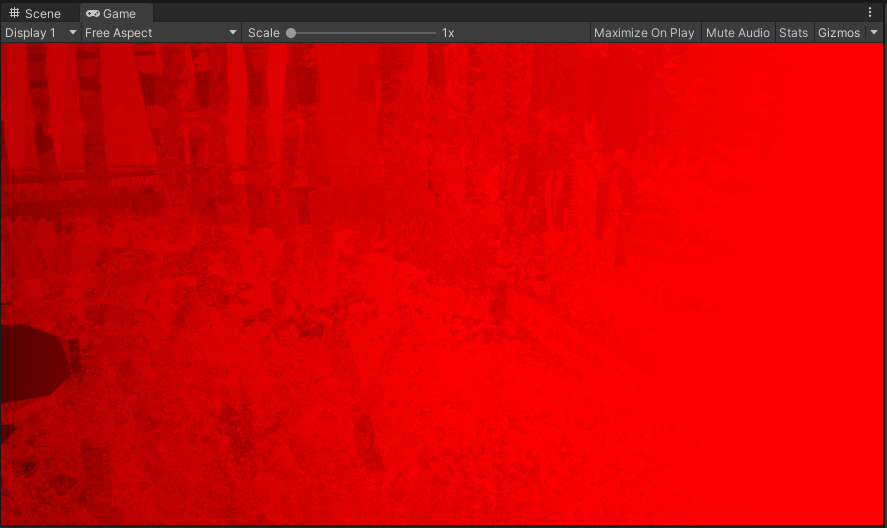
If you save your changes and go back to Unity, you’ll probably get some warnings and exceptions. However, if you disable and re-enable the Oil Painting Effect render feature in the Inspector, they should disappear, and you should see your structure tensor map from before, sort of:
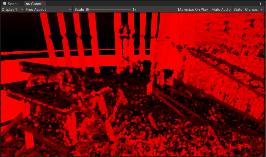
Welcome to Hell.
Before we make any changes to our shader though, we need a noise texture to plug into our settings. Here’s the noise texture that I’m using in my example:
A 128x128 noise texture.
When importing your noise, you’ll need to change some of the texture settings in the Inspector:
- Uncheck the sRGB (Color Texture) checkbox.
- Uncheck the Generate Mip Maps checkbox.
- Set the Filter Mode to Point (no filter).
Click Apply to update the texture settings.
Update your renderer feature settings (Settings > Edge Flow Settings > Noise Texture) to reference your noise texture.
Now we can go back to the shader code.
To start with, we’ll need some #defines:
 HLSLPROGRAM
 #include "Packages/com.unity.render-pipelines.universal/ShaderLibrary/SurfaceInput.hlsl"
 #include "Packages/com.unity.render-pipelines.core/ShaderLibrary/Color.hlsl"

+#define SCREEN_WIDTH _ScreenParams.x
+#define SCREEN_HEIGHT _ScreenParams.y
+#define SCREEN_SIZE _ScreenParams.xy
+#define PIXEL_X (_ScreenParams.z - 1)
+#define PIXEL_Y (_ScreenParams.w - 1)

 TEXTURE2D(_MainTex);
 SAMPLER(sampler_MainTex);
SCREEN_WIDTH and SCREEN_HEIGHT represent the width and height in pixels of the area being
rendered, which provides us with a way to convert from UV space to pixel space.
This is essentially the inverse of PIXEL_X and PIXEL_Y, which we’ve encountered before.
SCREEN_SIZE is just a float2 containing both of these values.
Now, we can create the function which generates our vector field:
 float2 SampleMain(float2 uv)
 {
     return SAMPLE_TEXTURE2D(_MainTex, sampler_MainTex, uv).rg;
 }

+float2 GetVectorField(float2 uv)
+{
+    float2 g = SampleMain(uv);
+
+    float norm = length(g);
+
+    return norm == 0 ? float2(0, 0) : g / norm;
+}

 half4 frag(Varyings input) : SV_Target
 {
     return half4(1 - SampleMain(input.uv), 0);
 }
Now we need to be able to sample the noise in the shader.
This is pretty straightforward to do, as we already have _MainTex as a reference.
Firstly, we’ll create the property so that it can be assigned in our material:
 Properties
 {
     _MainTex ("Texture", 2D) = "white" {}
+    [NoScaleOffset] _NoiseTex ("Noise Texture", 2D) = "white" {}
 }
We’re using the [NoScaleOffset] annotation here because we’ll be handling scaling and tiling
ourselves in the code.
Next, we need to make the noise texture available to the shader.
We can do this in the same way that we have for _MainTex, with one caveat - we also need the
texel information.
Conveniently, we only have to declare a variable with the correct name and type and Unity will
automatically supply this information for us:
 TEXTURE2D(_MainTex);
 SAMPLER(sampler_MainTex);

+TEXTURE2D(_NoiseTex);
+SAMPLER(sampler_NoiseTex);
+float4 _NoiseTex_TexelSize;

 struct Attributes
 {
Then, we can create a function similar to SampleMain to allow us to sample the noise texture:
 float3 SampleMain(float2 uv)
 {
     return SAMPLE_TEXTURE2D(_MainTex, sampler_MainTex, uv);
 }

+float3 SampleNoise(float2 uv)
+{
+    float x = uv.x * SCREEN_WIDTH / _NoiseTex_TexelSize.z;
+    float y = uv.y * SCREEN_HEIGHT / _NoiseTex_TexelSize.w;
+    return SAMPLE_TEXTURE2D(_NoiseTex, sampler_NoiseTex, float2(x, y));
+}

 float2 GetVectorField(float2 uv)
 {
     float2 g = SampleMain(uv);

     float norm = length(g);

     return norm == 0 ? float2(0, 0) : g / norm;
 }
If you want to check that this is working, you can replace 1 - SampleMain(input.uv) with
SampleNoise(input.uv) in the frag method.
In the Game view, you should see a tiled version of your noise texture (although it’ll be red,
as we’re only using a single channel for our render texture):
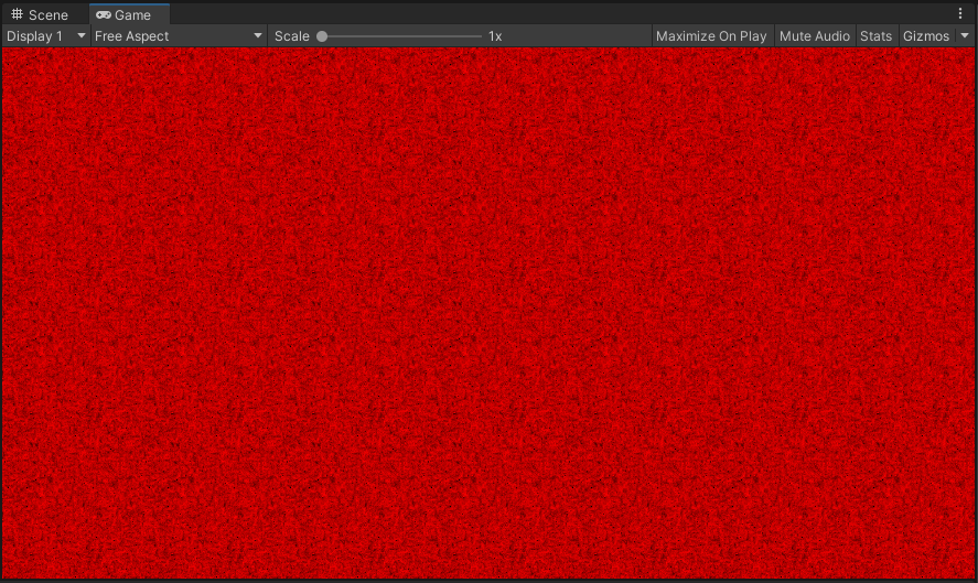
Red noise. It’s like white noise, but, well, red.
Now that we have our vector field and our noise texture, we’re pretty close to being able to put our edge flow map together. However, we still need a couple more utility functions first:
 float2 GetVectorField(float2 uv)
 {
     float2 g = SampleMain(uv);

     float norm = length(g);

     return norm == 0 ? float2(0, 0) : g / norm;
 }

+float2 QuantizeToPixel(float2 uv)
+{
+    return floor(uv * SCREEN_SIZE) / SCREEN_SIZE;
+}
+
+bool InBounds(float2 uv)
+{
+    float2 clamped = saturate(uv);
+    return clamped == uv;
+}

 half4 frag(Varyings input) : SV_Target
 {
     return half4(1 - SampleMain(input.uv), 0);
 }
These two functions are pretty self-explanatory - QuantizeToPixel snaps the current UV coordinate
to the nearest pixel value, and InBounds checks to see whether or not the current UV coordinate
is within the visible region of the screen.
The next one is a little more complex:
 bool InBounds(float2 uv)
 {
     float2 clamped = saturate(uv);
     return clamped == uv;
 }

+float2 FilterKernel(float2 uv, float kernelStrength)
+{
+    float2 v = GetVectorField(uv);
+    float2 k1 = v * kernelStrength;
+
+    v = GetVectorField(uv + 0.5f * k1);
+    float2 k2 = v * kernelStrength;
+
+    v = GetVectorField(uv + 0.5f * k2);
+    float2 k3 = v * kernelStrength;
+
+    v = GetVectorField(uv + k3);
+    float2 k4 = v * kernelStrength;
+
+    return uv + (k1 / 6.0f) + (k2 / 3.0f) + (k3 / 3.0f) + (k4 / 6.0f);
+}

 half4 frag(Varyings input) : SV_Target
 {
     return half4(1 - SampleMain(input.uv), 0);
 }
This is our filter kernel.
It samples along the vector field and provides a sort of “stream line gradient” across it.
To see the difference between the original vector field and the output of the filter kernel, you
can replace the return value of frag with half4(GetVectorField(input.uv), 0, 0) or
half4(FilterKernel(input.uv, 0.5f), 0, 0) respectively.
The original vector field (top) compared to the filter kernel output (bottom).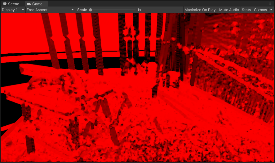
Now we can move onto the edge flow algorithm itself. We’ll need a couple of properties to configure it:
 Properties
 {
     _MainTex ("Texture", 2D) = "white" {}
     [NoScaleOffset] _NoiseTex ("Noise Texture", 2D) = "white" {}

+    [IntRange] _StreamLineLength ("Stream Line Length", Range(1, 64)) = 10
+    _KernelStrength ("Stream Kernel Strength", Range(0, 2)) = 0.5
 }
And the relevant declarations to make it accessible to the shader:
 TEXTURE2D(_NoiseTex);
 SAMPLER(sampler_NoiseTex);
 float4 _NoiseTex_TexelSize;

+int _StreamLineLength;
+float _KernelStrength;

 struct Attributes
 {
     float4 positionOS : POSITION;
     float2 uv         : TEXCOORD0;
 };
And finally, an additional #define so that we can make use of some arrays:
 #define SCREEN_WIDTH _ScreenParams.x
 #define SCREEN_HEIGHT _ScreenParams.y
 #define SCREEN_SIZE _ScreenParams.xy
 #define PIXEL_X (_ScreenParams.z - 1)
 #define PIXEL_Y (_ScreenParams.w - 1)

+#define MAX_LENGTH 64

 TEXTURE2D(_MainTex);
 SAMPLER(sampler_MainTex);
You may notice that the value of MAX_LENGTH is the same as the upper bound on our
_StreamLineLength range.
This is no accident: we will be using _StreamLineLength as a loop control variable, so
MAX_LENGTH needs to be great enough that we don’t run outside of our array bounds.
We now have everything we need to implement the edge flow algorithm, so without further ado, here it is:
 half4 frag(Varyings input) : SV_Target
 {
-    return half4(1 - SampleMain(input.uv), 0, 0);
+    // Compute stream line
+    float2 forwardStream[MAX_LENGTH];
+    float2 backwardStream[MAX_LENGTH];
+
+    float2 forward = input.uv;
+    float2 backward = input.uv;
+
+    for (int i = 0; i < _StreamLineLength; i++)
+    {
+        float kernelStrength = _KernelStrength * PIXEL_X;
+
+        forward = FilterKernel(forward, kernelStrength);
+        forwardStream[i] = forward;
+
+        backward = FilterKernel(backward, -kernelStrength);
+        backwardStream[i] = backward;
+    }
+
+    for (i = 0; i < _StreamLineLength; i++)
+    {
+        forwardStream[i] = QuantizeToPixel(forwardStream[i]);
+        backwardStream[i] = QuantizeToPixel(backwardStream[i]);
+    }
+
+    // Integrate stream line
+    float3 integral = float3(0, 0, 0);
+    int k = 0;
+
+    for (i = 0; i < _StreamLineLength; i++)
+    {
+        float2 xi = forwardStream[i];
+        if (InBounds(xi))
+        {
+            integral += SampleNoise(xi);
+            k++;
+        }
+
+        xi = backwardStream[i];
+        if (InBounds(xi))
+        {
+            integral += SampleNoise(xi);
+            k++;
+        }
+    }
+    integral /= k;
+
+    return half4(integral, 0);
 }
Save the changes, and you can see the noise being distorted by the vector field:
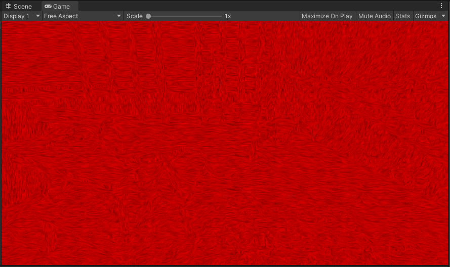
The convolved noise.
We’re almost done now. All that’s left is…
Putting it all together
To produce our final effect, we need two things: a depth map and a compositing shader.
Getting the depth map is pretty easy, as Unity already provides a way for us to access it using a
DepthOnlyPass.
We’ll add it to our renderer feature:
 public class OilPaintingEffect : ScriptableRendererFeature
 {
+    private static readonly LayerMask AllLayers = ~0;

     private const int FilterKernelSize = 32;

     public Settings settings;

+    private DepthOnlyPass depthOnlyPass;
     private OilPaintingEffectPass renderPass;

+    private RenderTargetHandle depthTexture;

     public override void AddRenderPasses(ScriptableRenderer renderer, ref RenderingData renderingData)
     {
+        if (Application.isEditor && (renderingData.cameraData.camera.name == "SceneCamera" || renderingData.cameraData.camera.name == "Preview Scene Camera"))
+        {
+            return;
+        }
+
+        depthOnlyPass.Setup(renderingData.cameraData.cameraTargetDescriptor, depthTexture);
+        renderer.EnqueuePass(depthOnlyPass);

         renderPass.Setup(settings);
         renderer.EnqueuePass(renderPass);
     }

     public override void Create()
     {
         var structureTensorMaterial = CoreUtils.CreateEngineMaterial("Hidden/Oil Painting/Structure Tensor");
         var kuwaharaFilterMaterial = CoreUtils.CreateEngineMaterial("Hidden/Oil Painting/Anisotropic Kuwahara Filter");
         var lineIntegralConvolutionMaterial = CoreUtils.CreateEngineMaterial("Hidden/Oil Painting/Line Integral Convolution");

         renderPass = new OilPaintingEffectPass(structureTensorMaterial,
                                                kuwaharaFilterMaterial,
                                                lineIntegralConvolutionMaterial);

         renderPass.renderPassEvent = RenderPassEvent.BeforeRenderingPostProcessing;

         var texture = new Texture2D(FilterKernelSize, FilterKernelSize, TextureFormat.RFloat, true);
         InitializeFilterKernelTexture(texture,
                                       FilterKernelSize,
                                       settings.anisotropicKuwaharaFilterSettings.filterKernelSectors,
                                       settings.anisotropicKuwaharaFilterSettings.filterKernelSmoothness);

         settings.anisotropicKuwaharaFilterSettings.filterKernelTexture = texture;

+        depthOnlyPass = new DepthOnlyPass(RenderPassEvent.BeforeRenderingPostProcessing,
+                                          RenderQueueRange.all,
+                                          AllLayers);
+
+        depthTexture.Init("_CameraDepthTexture");
     }
The if statement at the start of AddRenderPasses is just to check whether or not we’re in the
Scene view, and to skip our post-processing effect if we are.
It’s not necessary to include if you’d like to see the effect in the Scene view, but I find that
it’s more convenient to have it disabled there.
But now we have access to the depth information in our scene, which we’ll need for our compositing
shader.
Speaking of which, we’ll create that now
(Assets > Create > Shader > Image Effect Shader) and call it
OilPaintingEffectCompositor.
Replace its contents with this:
Shader "Hidden/Oil Painting/Compositor"
{
    Properties
    {
        _MainTex ("Texture", 2D) = "white" {}
        _EdgeFlowTex ("Edge Flow", 2D) = "white" {}
        _DepthTex ("Depth", 2D) = "white" {}

        _EdgeContribution ("Edge Contribution", Range(0, 4)) = 1
        _FlowContribution ("Flow Contribution", Range(0, 4)) = 1
        _DepthContribution ("Depth Contribution", Range(0, 4)) = 1

        _BumpPower ("Bump Power", Range(0.25, 1)) = 0.8
        _BumpIntensity("Bump Intensity", Range(0, 1)) = 0.4
    }
    SubShader
    {
        Tags { "RenderType"="Opaque" }
        LOD 200

        Pass
        {
            HLSLPROGRAM
            #include "Packages/com.unity.render-pipelines.universal/ShaderLibrary/SurfaceInput.hlsl"
            #include "Packages/com.unity.render-pipelines.core/ShaderLibrary/Color.hlsl"

            #define PIXEL_X (_ScreenParams.z - 1)
            #define PIXEL_Y (_ScreenParams.w - 1)

            TEXTURE2D(_CameraDepthTexture);
            SAMPLER(sampler_CameraDepthTexture);

            TEXTURE2D(_MainTex);
            SAMPLER(sampler_MainTex);

            TEXTURE2D(_EdgeFlowTex);
            SAMPLER(sampler_EdgeFlowTex);

            TEXTURE2D(_DepthTex);
            SAMPLER(sampler_DepthTex);

            float _EdgeContribution;
            float _FlowContribution;
            float _DepthContribution;

            float _BumpPower;
            float _BumpIntensity;

            struct Attributes
            {
                float4 positionOS : POSITION;
                float2 uv         : TEXCOORD0;
            };

            struct Varyings
            {
                float2 uv     : TEXCOORD0;
                float4 vertex : SV_POSITION;
            };

            Varyings vert(Attributes input)
            {
                Varyings output = (Varyings)0;

                VertexPositionInputs vertexInput = GetVertexPositionInputs(input.positionOS.xyz);
                output.vertex = vertexInput.positionCS;
                output.uv = input.uv;

                return output;
            }

            float SampleDepth(float2 uv)
            {
                return SAMPLE_DEPTH_TEXTURE(_CameraDepthTexture, sampler_CameraDepthTexture, uv);
            }

            float3 SampleMain(float2 uv)
            {
                return SAMPLE_TEXTURE2D(_MainTex, sampler_MainTex, uv).rgb;
            }

            float SampleEdgeFlow(float2 uv)
            {
                return SAMPLE_TEXTURE2D(_EdgeFlowTex, sampler_EdgeFlowTex, uv).r;
            }

            float3 SobelU(float2 uv)
            {
                return (
                    -1.0f * SampleMain(uv + float2(-PIXEL_X, -PIXEL_Y)) +
                    -2.0f * SampleMain(uv + float2(-PIXEL_X, 0)) +
                    -1.0f * SampleMain(uv + float2(-PIXEL_X, PIXEL_Y)) +

                    1.0f * SampleMain(uv + float2(PIXEL_X, -PIXEL_Y)) +
                    2.0f * SampleMain(uv + float2(PIXEL_X, 0)) +
                    1.0f * SampleMain(uv + float2(PIXEL_X, PIXEL_Y))
                ) / 4.0;
            }

            float3 SobelV(float2 uv)
            {
                return (
                    -1.0f * SampleMain(uv + float2(-PIXEL_X, -PIXEL_Y)) +
                    -2.0f * SampleMain(uv + float2(0, -PIXEL_Y)) +
                    -1.0f * SampleMain(uv + float2(PIXEL_X, -PIXEL_Y)) +

                    1.0f * SampleMain(uv + float2(-PIXEL_X, PIXEL_Y)) +
                    2.0f * SampleMain(uv + float2(0, PIXEL_Y)) +
                    1.0f * SampleMain(uv + float2(PIXEL_X, PIXEL_Y))
                ) / 4.0;
            }

            float GetHeight(float2 uv)
            {
                float3 edgeU = SobelU(uv);
                float3 edgeV = SobelV(uv);
                float edgeFlow = SampleEdgeFlow(uv);
                float depth = SampleDepth(uv);

                return _EdgeContribution * (length(edgeU) + length(edgeV)) +
                    _FlowContribution * edgeFlow +
                    _DepthContribution * depth;
            }

            half4 frag(Varyings input) : SV_Target
            {
                float3 baseColor = SampleMain(input.uv);

                float bumpAbove = GetHeight(input.uv + float2(0, PIXEL_Y));
                float bump = GetHeight(input.uv);

                float diff = bump - bumpAbove;
                diff = sign(diff) * pow(saturate(abs(diff)), _BumpPower);

                return half4(baseColor + baseColor * diff * _BumpIntensity, 0);
            }

            #pragma vertex vert
            #pragma fragment frag

            ENDHLSL
        }
    }
}
So what’s happening in the compositor? It’s actually fairly straightforward: we take the filtered image and perform edge detection using the Sobel filter, and then blend it with the edge flow map and the depth map to get a height map. This height map is then used in a very simple bump mapping algorithm which lightens or darkens each pixel depending on whether the one above has a greater height. This gives us our final image, which has the impression of brush strokes.
So all we need to do now is add some new settings to the renderer feature and include the compositing in our render pass, and our effect is complete!
So, let’s get the settings out of the way first:
 [Serializable]
 public class Settings
 {
     public AnisotropicKuwaharaFilterSettings anisotropicKuwaharaFilterSettings;
     public EdgeFlowSettings edgeFlowSettings;
+    public CompositorSettings compositorSettings;
 }

 [Serializable]
 public class AnisotropicKuwaharaFilterSettings
 {
     [Range(3, 8)]
     public int filterKernelSectors = 8;
     [Range(0f, 1f)]
     public float filterKernelSmoothness = 0.33f;
     [NonSerialized]
     public Texture2D filterKernelTexture;

     [Range(2f, 12f)]
     public float filterRadius = 4f;
     [Range(2f, 16f)]
     public float filterSharpness = 8f;
     [Range(0.125f, 8f)]
     public float eccentricity = 1f;

     [Range(1, 4)]
     public int iterations = 1;
 }

 [Serializable]
 public class EdgeFlowSettings
 {
     public Texture2D noiseTexture;

     [Range(1, 64)]
     public int streamLineLength = 10;
     [Range(0f, 2f)]
     public float streamKernelStrength = 0.5f;
 }

+[Serializable]
+public class CompositorSettings
+{
+    [Range(0f, 4f)]
+    public float edgeContribution = 1f;
+    [Range(0f, 4f)]
+    public float flowContribution = 1f;
+    [Range(0f, 4f)]
+    public float depthContribution = 1f;
+
+    [Range(0.25f, 1f)]
+    public float bumpPower = 0.8f;
+    [Range(0f, 1f)]
+    public float bumpIntensity = 0.4f;
+}
Now we’ll set up the material and send it to the render pass via its constructor:
 public override void Create()
 {
     var structureTensorMaterial = CoreUtils.CreateEngineMaterial("Hidden/Oil Painting/Structure Tensor");
     var kuwaharaFilterMaterial = CoreUtils.CreateEngineMaterial("Hidden/Oil Painting/Anisotropic Kuwahara Filter");
     var lineIntegralConvolutionMaterial = CoreUtils.CreateEngineMaterial("Hidden/Oil Painting/Line Integral Convolution");
+    var compositorMaterial = CoreUtils.CreateEngineMaterial("Hidden/Oil Painting/Compositor");

     renderPass = new OilPaintingEffectPass(structureTensorMaterial,
                                            kuwaharaFilterMaterial,
-                                           lineIntegralConvolutionMaterial);
+                                           lineIntegralConvolutionMaterial,
+                                           compositorMaterial);

     renderPass.renderPassEvent = RenderPassEvent.BeforeRenderingPostProcessing;

     var texture = new Texture2D(FilterKernelSize, FilterKernelSize, TextureFormat.RFloat, true);
     InitializeFilterKernelTexture(texture,
                                   FilterKernelSize,
                                   settings.anisotropicKuwaharaFilterSettings.filterKernelSectors,
                                   settings.anisotropicKuwaharaFilterSettings.filterKernelSmoothness);

     settings.anisotropicKuwaharaFilterSettings.filterKernelTexture = texture;

     depthOnlyPass = new DepthOnlyPass(RenderPassEvent.BeforeRenderingPostProcessing,
                                       RenderQueueRange.all,
                                       AllLayers);

     depthTexture.Init("_CameraDepthTexture");
 }
And now we’re pretty close. Let’s update the fields and the constructor for our render pass:
 private RenderTargetIdentifier source;
 private RenderTargetIdentifier destination;

 private RenderTexture structureTensorTex;
 private RenderTexture kuwaharaFilterTex;
 private RenderTexture edgeFlowTex;

 private readonly Material structureTensorMaterial;
 private readonly Material kuwaharaFilterMaterial;
 private readonly Material lineIntegralConvolutionMaterial;
+private readonly Material compositorMaterial;

 private int kuwaharaFilterIterations = 1;

 public OilPaintingEffectPass(Material structureTensorMaterial,
                              Material kuwaharaFilterMaterial,
-                             Material lineIntegralConvolutionMaterial)
+                             Material lineIntegralConvolutionMaterial,
+                             Material compositorMaterial)
 {
     this.structureTensorMaterial = structureTensorMaterial;
     this.kuwaharaFilterMaterial = kuwaharaFilterMaterial;
     this.lineIntegralConvolutionMaterial = lineIntegralConvolutionMaterial;
+    this.compositorMaterial = compositorMaterial;
 }
And create an additional setup method:
 public void Setup(OilPaintingEffect.Settings settings)
 {
     SetupKuwaharaFilter(settings.anisotropicKuwaharaFilterSettings);
     SetupLineIntegralConvolution(settings.edgeFlowSettings);
+    SetupCompositor(settings.compositorSettings);
 }

 private void SetupKuwaharaFilter(OilPaintingEffect.AnisotropicKuwaharaFilterSettings kuwaharaFilterSettings)
 {
     kuwaharaFilterMaterial.SetInt("_FilterKernelSectors", kuwaharaFilterSettings.filterKernelSectors);
     kuwaharaFilterMaterial.SetTexture("_FilterKernelTex", kuwaharaFilterSettings.filterKernelTexture);
     kuwaharaFilterMaterial.SetFloat("_FilterRadius", kuwaharaFilterSettings.filterRadius);
     kuwaharaFilterMaterial.SetFloat("_FilterSharpness", kuwaharaFilterSettings.filterSharpness);
     kuwaharaFilterMaterial.SetFloat("_Eccentricity", kuwaharaFilterSettings.eccentricity);
     kuwaharaFilterIterations = kuwaharaFilterSettings.iterations;
 }

 private void SetupLineIntegralConvolution(OilPaintingEffect.EdgeFlowSettings edgeFlowSettings)
 {
     lineIntegralConvolutionMaterial.SetTexture("_NoiseTex", edgeFlowSettings.noiseTexture);
     lineIntegralConvolutionMaterial.SetInt("_StreamLineLength", edgeFlowSettings.streamLineLength);
     lineIntegralConvolutionMaterial.SetFloat("_StreamKernelStrength", edgeFlowSettings.streamKernelStrength);
 }

+private void SetupCompositor(OilPaintingEffect.CompositorSettings compositorSettings)
+{
+    compositorMaterial.SetFloat("_EdgeContribution", compositorSettings.edgeContribution);
+    compositorMaterial.SetFloat("_FlowContribution", compositorSettings.flowContribution);
+    compositorMaterial.SetFloat("_DepthContribution", compositorSettings.depthContribution);
+    compositorMaterial.SetFloat("_BumpPower", compositorSettings.bumpPower);
+    compositorMaterial.SetFloat("_BumpIntensity", compositorSettings.bumpIntensity);
+}

 public override void OnCameraSetup(CommandBuffer cmd, ref RenderingData renderingData)
 {
     RenderTextureDescriptor blitTargetDescriptor = renderingData.cameraData.cameraTargetDescriptor;
     blitTargetDescriptor.depthBufferBits = 0;
And then finally, we can update the Execute method:
 public override void Execute(ScriptableRenderContext context, ref RenderingData renderingData)
 {
     CommandBuffer cmd = CommandBufferPool.Get("Oil Painting Effect");

     Blit(cmd, source, structureTensorTex, structureTensorMaterial, -1);

     kuwaharaFilterMaterial.SetTexture("_StructureTensorTex", structureTensorTex);

     Blit(cmd, source, kuwaharaFilterTex, kuwaharaFilterMaterial, -1);
     for (int i = 0; i < kuwaharaFilterIterations - 1; i++)
     {
         Blit(cmd, kuwaharaFilterTex, kuwaharaFilterTex, kuwaharaFilterMaterial, -1);
     }

     Blit(cmd, structureTensorTex, edgeFlowTex, lineIntegralConvolutionMaterial, -1);

-    Blit(cmd, edgeFlowTex, destination);
+    compositorMaterial.SetTexture("_EdgeFlowTex", edgeFlowTex);
+
+    Blit(cmd, kuwaharaFilterTex, destination, compositorMaterial, -1);

     context.ExecuteCommandBuffer(cmd);
     CommandBufferPool.Release(cmd);
 }
And now we can see our masterpiece in all its glory:
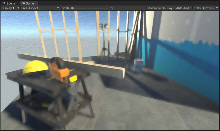
Every frame a painting. Literally.
Wrapping up
We’ve now fully implemented our image effect, and it looks pretty good. There are many parameters to play around with to help you find the best balance of performance and aesthetics for your needs.
Of course, there are always improvements that can be made, both technically and aesthetically - we could perform Gaussian blurs in two passes to achieve O(N) complexity instead of O(N2), for example, or improve the bump mapping to get more realistic looking results. Another option would be to improve the Kuwahara filter algorithm to support different filter sizes based on the depth map.
These improvements are left as an exercise to the reader for now, however, as I think the effect is good enough for my purposes and I want to move on to other aspects of my prototype. As I mentioned before, I may revisit this topic at some point, particularly if I think of a neat solution to the technical limitations I ran into during this process.